Herman Miller Sit/Stand Desk Control
A while ago I got myself a sit/stand desk. The idea was that if you are spending 8 - 12 hours a day working behind a computer, it might help if you can alternate sitting with standing. That has proven to be very helpful, however I did have one gripe with the desk.
The control to raise and lower the desk is a lever that you either push down to lower the desk, or pull up to raise it. You can program start and stop values, so that the desk only lowers to the low setpoint and raises to the high setpoint. However you need to keep the lever engaged until the desk reaches its position. This takes about 11 seconds. Even the advanced electronic control option that you can order for the desk requires you to keep the button pressed until the desk reaches its setpoint. So stupid.
I decided to fix this the hard way. I opened up the lever control mechanism to determine exactly what makes the desk engage when you toggle the lever.
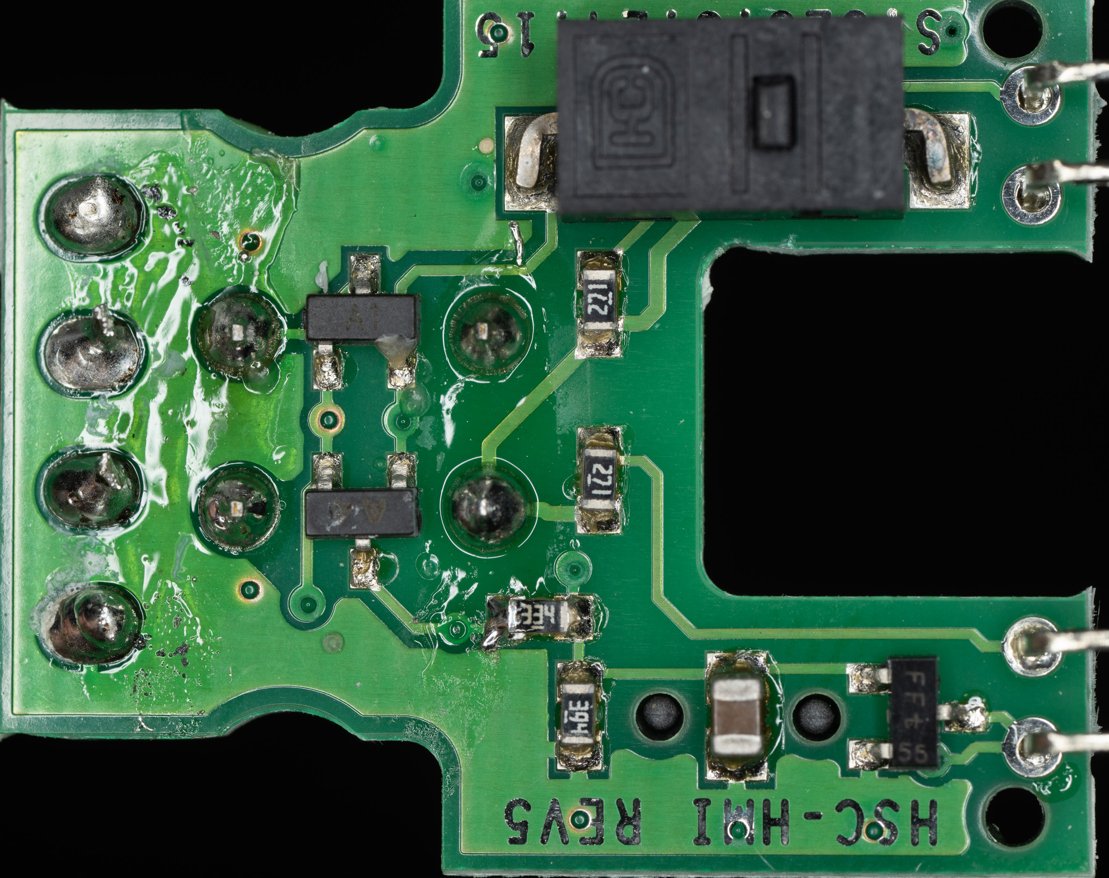
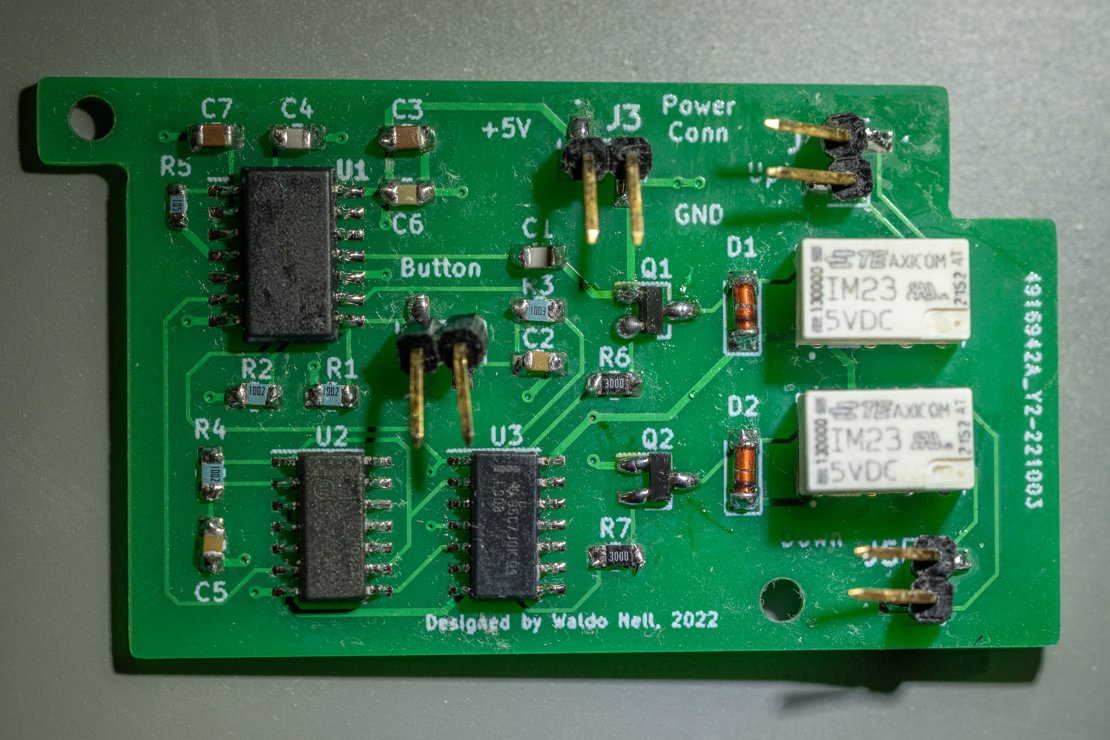
The flipside of this PCB is symmetric except for the programming button. Analysing this, it is clear that when the lever is engaged, it pushes mechanically against the small push button on the top right, which just closes the circuit and that signal is sent to the desk controller located elsewhere. A similar thing happens for the other direction - the lever pushes against a button on the underside of this PCB, closing a different circuit.
If I can design an electronic circuit that, when a momentary push button is pressed, a relay closes for 12 seconds, then remember its state, so that on the next push of the button a different relay is engaged for 12 seconds, I can resolve the issue of having to keep a button pressed.
The logical route is a 30c microcontroller and some basic support circuitry but I decided to use basic gates and a bit of suffering.
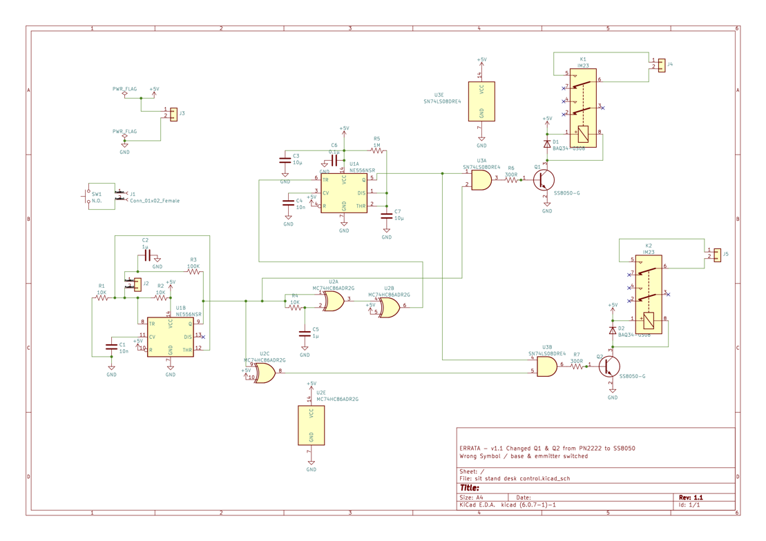
In the schematic you can see 4 functional pieces. U1A is one 555 timer that is configured as a monostable multivibrator - also known as a one shot timer. Each time pin 6 is taken high, it will take the output high for a duration determined by the time constant formed by R5 and C7. The formula for the time constant is τ = 1.1 * R5 * C7. Since I wanted the desk to be engaged for about 11 seconds I picked τ = 1.1 * 1E6 * 10E-6 = 11 seconds.
The output of this circuit can drive one relay (the circuitry near Q1/K1), which can "close" the switch of the desk control PCB. However it cannot toggle state and trigger a different relay alternatively. For that I decided to add some additional logic. I inserted a flip flop circuit using another 555 timer in front of the one shot timer. A push button is connected to the trigger input, and each time it is pressed the output at pin 9 will be latched high and low, alternatively. This is how I keep state. This output feeds in to a XOR gate configured as a dual edge triggered pulse, and the output is inverted (remember I need to pull the trigger low to activate U1A). This output feeds U1A, and the output from U1B is AND-ed with the output of U1A via U3A and U3B to only trigger the relay that should be triggered at each cycle. The outputs of these two TTL gates are fed into a standard NPN transistor with a flyback diode to drive a small IM23 SMD relay.
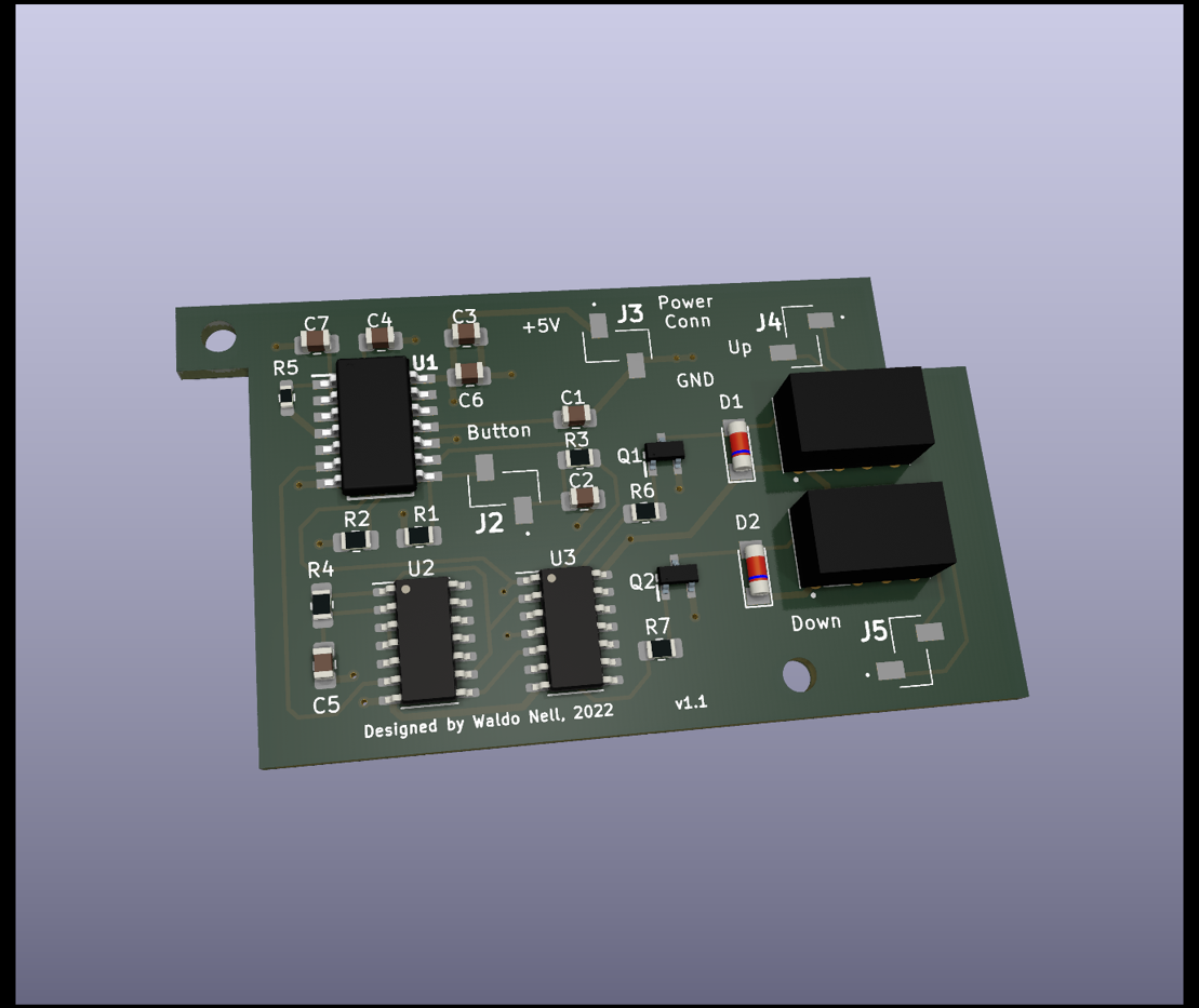
The 3D rendering of the PCB layout reflects the constraints the small box I had lying around placed on the design, and to fit all the components I needed to use SMD parts. The actual control board is tiny - measuring 54mm x 33mm. The circuit was designed in KiCAD, same with the PCB and I had JLPCB create the actual PCB. It cost me $2 for 5 PCBs, even though I only needed one.
So once hooked up I tested it. Pressing the button correctly raised the desk, however it stopped short by 1 second. Pressing it again and the desk lowered - exactly right. However when it reached the bottom position, it would always immediately bounce upward again and raise the desk. Whoopsies...
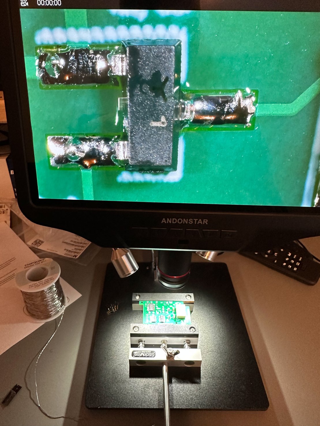
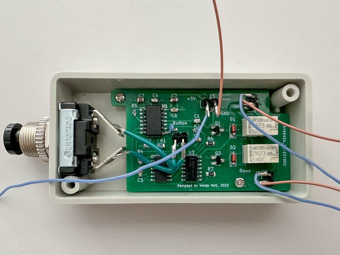
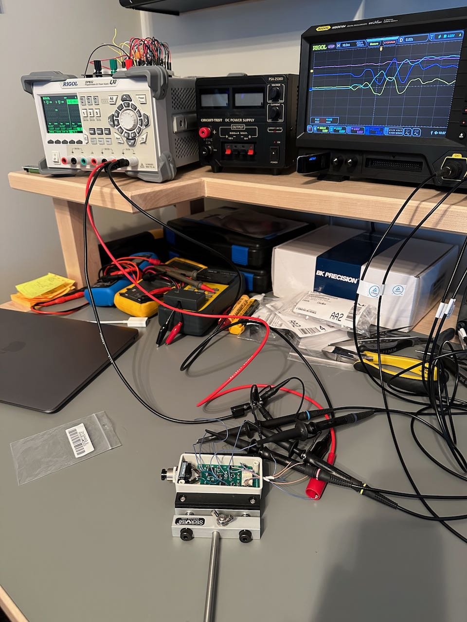
I took the circuit down and hooked it up to my workbench equipment after soldering a bunch of test leads.
I found that on one of the state changes, the system would oscillate for 35µs until it reached a steady state.
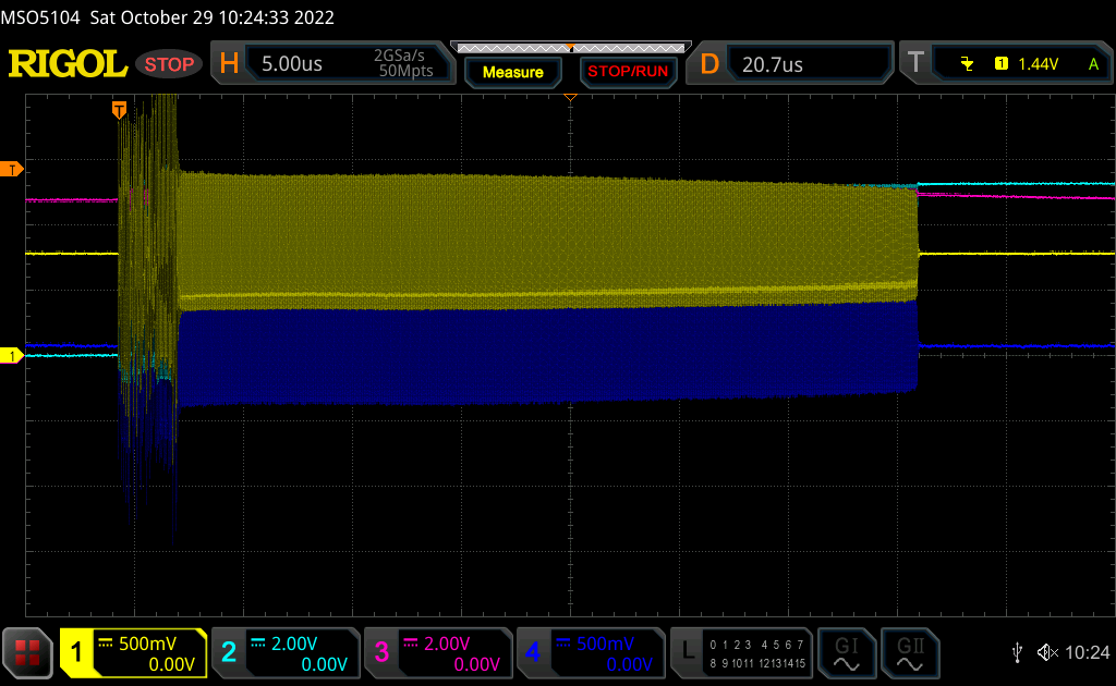
This concerned me, and I thought it could be the culprit. Now I have not been using Schmitt triggered XOR gates, so my analogue pulse generator in U2A was causing these oscillations when the input voltage was in the no-go zone between a logic 1 and 0. I ordered a Schmitt based XOR gate to replace this package, however while I was waiting for it to arrive I realised that it was most likely not the culprit. I probed the actual relays and saw that they never activated out of design parameters, even with the oscillation. That made sense because the oscillation being 35µs in duration was not long enough to turn on the NPN transistor and energise the relay coil. It was definitely unwanted and would fail any EMI compliance, but it was not the cause of the unwanted behaviour I was trying to pin down.
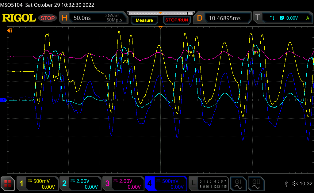
The dark blue signal is the base voltage of Q1. Yellow is base voltage of Q2. During these oscillations the base voltages exceed 1V, enough to turn on the transistor. But the duration of these pulses are a couple of tens of nanoseconds - not enough to energise the relays.
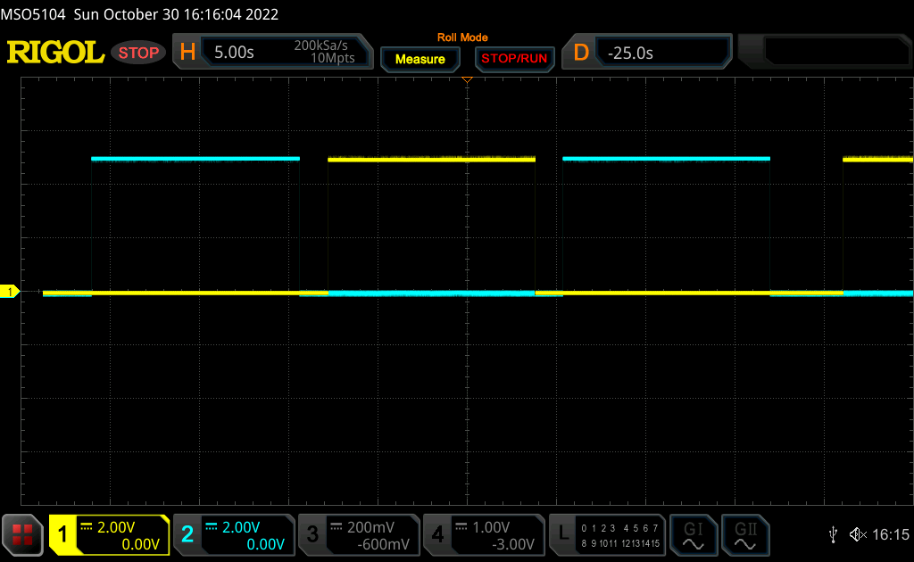
The cyan is output of relay K1, yellow is output of K2. It shows how the outputs alternate when I push the toggle button. I cannot get it to toggle on its own after it ended the cycle.
I then decided to not be a n00b and read some datasheets. I did not think of it at the time, but I realised I left the inputs to the unused CMOS XOR gate floating - this is a big no-no in electronic design. So I started with three modifications to the board:
- I pulled U2D pins 12 and 13 high
- I added a 0.1µF bypass capacitor to U2 and U3
- I also added a 100µF capacitor across Vcc and ground at the power input terminals.
My reasoning was that somehow the power supply from the sit/stand desk must behave differently than my bench power supply - perhaps because my bench power supply had short leads to the circuit and the desk had a long lead, the CMOS and TTL chips could not suck enough current during transitions and thereby causing instabilities?
With these changes alone I mounted the circuit back on the desk, and probed the Vcc rail from the sit/stand desk directly. During the lowering of the desk, when it stops, this is the only ripple I could see:
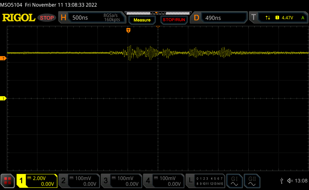
The ripple is very little, and not long enough to cause issues.
Testing it again after these modifications resulted in success. The last modification I made was to solder a 330kΩ resistor in series with R5 after cutting the track between R5 and U1A pin 5, to increase the time constant to 14 seconds.