100W 3-way Speaker Design
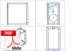
Enclosure - CAD Diagram
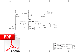
3-Way Crossover Network
Crossover - Schematic Diagram
As I have explained in the introduction to electronics, I have designed my own speaker system that sounds (in my opinion) quite good. I have designed this long before I had any proper electronic experience and knowledge. However, when I simulated the crossover's response in PSpice a few years ago, I found that it did not have any peaks in the responses and that the overlapping regions of the frequency response were smooth and without oscillations.
This proved that the crossover design was - although not designed from start to end using strict engineering principles - mathematically sound. It also proved why they sounded so good.
In this article I want to take the speakers I have designed as an example to describe the general speaker design process. I must first just clearly state I am no audiophile expert, neither an expert in speaker designing. I have read extensively on the subject however, and had quite a bit of practical experience.
To design a speaker system, it is possible to divide the work into four distinct phases. The first phase is the specification and design phase, the second is the building of the boxes, the third is the design of the crossover network and the last the assembly phase. It is important to note that the phases mentioned do not follow a linear process - it has some iterative processes whereby the speaker system is optimised and tuned.
Specification and Design Phase
In this phase one needs to decide exactly what you want to build, how you want to build it and lastly determine the compatibility and integration issues with your existing system (if any). There are several questions you should ask yourself before starting the design. Here are the most important ones (assuming you do currently have a hi-fi system):
- What is the impedance of the amplifier?
- What is the power rating (true RMS - not PMPO) of the amplifier?
- Are you going to use bi/tri-wiring?
- Do you want large floor standing speakers or smaller ones?
- How many drivers do you want in your speaker system?
- What sizes do you want the drivers to be?
- How much money do you want to invest?
- Do you like softer, smoother sound rather than sharper, clearly defined?
- How many channels does your amplifier have?
Once you have proper answers to all these it is safe to proceed to the design phase. I am going to assume you have the same answers to those questions than I had (because I want to illustrate the design process). I will list my assumptions here (in order):
- Impedance: 8 ohms
- Amplifier Power Rating (per channel): 100W RMS
- Bi/tri-wiring: None
- Speaker Size: Medium
- Number of drivers: 3-Way system
- Sizes of drivers: 10" Bass Driver, 4" Midrange Driver and 1" Dome Tweeter
- Amount of money: Not much :)
- Sound preference: Like sharper, clearly defined sounds
- Amount of channels: 2
Before you can start any design work, you need to specify and obtain the drivers for your speaker system. The design of the enclosure and crossover network depends critically on the parameters of the speakers as well as their dimensions.
I bought an unbranded 10", 8 ohm, 100W Bass Driver (Woofer), whose parameters I unfortunately never could have gotten hold of. The midrange unit is a 4", 8 ohm, 40W fully enclosed unit. Lastly, I bought a 1" metallic dome tweeter, rated at 30W and 4 ohms (I had to do with these drivers as I did not have much money at that stage).
Box Design Phase
Once I had these drivers, I could start with the box design (speakers tend to have different geometries and I needed the specific speakers in order to calculate the exact dimensions of the boxes). Loudspeaker enclosures are not mere boxes just there as mechanical support for the drivers. They are critical in the sound generation quality of the bass units. Note that contrary to popular belief, the enclosure's volume only has an effect on the bass driver - not on the midrange or tweeter units. In fact, those units need to be completely isolated from the interior air volume of the enclosure. Note that I am not implying the enclosure has no effect on midrange and treble sounds generated by the midrange and tweeter units. It does have an effect - but only with regards to the position on the enclosure's face panel - not with regards to the air volume contained in the box. On the contrary, the woofer is mostly affected by the air volume in the enclosure, and almost negligently on the location (for larger units - like subwoofers). In other words, the larger the driver (and lower the frequency of the reproduced sound), the less location plays a role and the more does the air volume of the enclosure, and the smaller the driver (and hence the higher the frequency) the more location plays a role and the less the air volume does.
Keeping this in mind, I started out with my box design. There are two main types of enclosures you can choose from. The one is a closed box, and the other is the vented enclosure. Which one you choose is pretty much up to you, although the vented enclosure is a bit more difficult to design properly. The vented enclosure reinforces the bass reproduction because of the 180° phase shift. It is also very well suited for bookshelf sized speakers where volume is limited. The enclosure should not have any other effect than to mechanically support the drivers. By this I mean it should not vibrate (adding noise to the sound), resonate, or move at all. This is obviously impossible to attain completely, but you must strive for that goal.
Three parameters are crucial in determining the frequency response of a loudspeaker. They are called the Small Signal Parameters, and are the compliance, Q and free-air resonance. Basically the compliance (Vas) is a measure of the overall stiffness of the cone, surround (the part that attaches the cone to the frame), and spider (the zig-zag material that attaches the rear of the cone to the frame). The Q (Qts) is a measure of the sharpness of the driver's free air resonance. Free-air resonance (Fs) is the resonant frequency of the driver's voice coil impedance when the driver is suspended in free air (no enclosure).
Because I had two no-name brand bass drivers on hand, I could not get any of these critical parameters' values. So the only way for me to go was to use common sense, experimenting and once again experimenting (I did not have access to equipment to determine these parameters - neither did I know properly how to determine them from scratch). I used a "typical" box dimension for a 10", 100W bass driver (if there is anything like such). The important thing is not to make the enclosure a cube. This will cause standing waves which is very bad for the frequency response. I used the dimensions 342mm x 620mm x 595mm (WxHxD). As you can see, the relationship is 0.55:1:0.96. Please not that this is the outside dimensions, the panels are 32mm thick and the interior is lined with acoustic panels having a thickness of 16mm. So the effective interior volume is less.
I wanted as primary goal a rigid as possible enclosure. Previous experience told me that this is of the utmost importance. The previous design utilised 16mm high density chipboard and had no reinforcing or any other mechanisms to assist in the mechanical rigidity of the enclosure. I had the same drivers mounted in these containers. I remember that I once put a glass full of champagne on top of the one box. Big ripples (transversal waves) were apparent on the surface of the champagne at high volumes. This told me intuitively that the boxes were vibrating - hence generating extra (unwanted) sounds that definitely influenced the sound quality. There were several other issues with those boxes as well that caused them to interfere with the sound.
So the road I took with the design of my new enclosures was to implement the following criteria:
- The panels must be rigid and sound proof
- The panels must be joined tightly (airtight)
- The panels must not vibrate at all - especially with respect to each other
- The area between the drivers and the surface of the face panel must be sealed
In order to realise my criteria, I used 32mm waterproof high density chipboard for all my panels. These are really heavy and caused the enclosures to be very heavy, but I was not concerned with that side effect. Next I joined them together with clear silicone. I was skeptical of this idea at first (my father suggested it) because when silicone dries it forms a rubbery substance. I was concerned that this would allow the panels to vibrate. Well, I was very amazed at the result. I did not use one single screw in the whole enclosure - all the panels were siliconed together - and this was one of the most rigid speaker boxes I have ever seen. The silicone joined the panels very securely, and the insignificant vibrations that were present, were absorbed into the rubbery silicone - something that would have caused an audible rattling noise. So my first three criteria's was met. In order to accomplish the last criteria, I used a special putty like substance in between the frames of the drivers and the face panel. This sealed the junction effectively.
In order to minimise internal standing waves and resonances, I had to add damping inside the enclosure. As a first step I added 16mm acoustic panels (those used in ceilings of some office buildings) to all the inner walls of the cabinet, except for the inner face panel. This greatly added to the damping I needed, but was not quite enough. Next I added some Think-Pink (fibreglass wool) to the inside. I tested this configuration in order to determine whether I had added enough Think-Pink. At first I was very confused because I had almost no bass at all! But a friend of mine Stuart (from SDA Acoustics) told me that I had too much damping. The box simply smothered all bass frequencies. So I removed some of the Think-Pink until I got a proper bass response. [I know this is a very crude method of building speakers, but it worked :)].
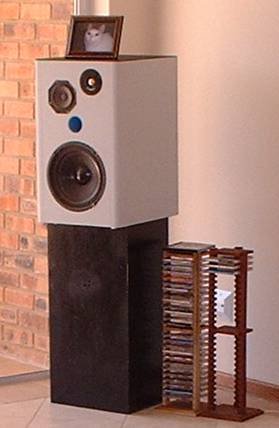
The final design of the loudspeaker enclosure can be seen in the first four figures to the upper left on this page. The first figure is the CAD drawing I made of the enclosure, the second the outline view, the third the shaded view and the last an actual photo of the finished enclosure. I forgot to add the length of the duct (for the ports) to the drawing. They should be 8" in length. Also, in order to decouple the speaker system from the environment, I added some spikes to the bottom of the enclosure.
Crossover Design Phase
A crossover is a collection of electronics that basically splits the frequency spectrum of the complete signal and provides the drivers with the frequency band it was designed for. I used a 3-way crossover network that is a combination of 6-th and 12-order design. The reason for this is that I did not want a sharp cutoff of frequency response between the bass and midrange drivers, but for the midrange-treble crossover I needed a steeper cutoff slope - I did not want to send any midrange frequencies to a dome tweeter incapable of responding to them, and thereby protecting them as well. The resistors are used to bring the different drivers' impedances more in line with each other so that they compliment each other better (they are from totally different manufacturers and were not made to compliment each other). The final design was a combination of applying theory and experimental listening sessions together with repetitive tuning. The bode plot of the gain versus frequency can be seen in the figure to the left. The woofer has a 12dB/octave slope, the midrange low band is at 6dB/octave, the high band cutoff slope is 12dB/octave and lastly, the tweeter has a cutoff slope of 12dB/octave.
The frequency response is not as flat as I had explained earlier in this article. The reason for this is that I had to reverse-engineer my crossovers from a very, very old schematic diagram I found in one of my electronic archives. Although I believe it is the correct diagram, I did not have access to the equivalent speaker circuit diagram and component values that I used in the design and when I simulated it with P-Spice. So I went back to basics, derived the Thevenin equivalent circuits for all the different drivers, substituted a "standard" equivalent driver circuit for the different drivers, calculated the s-plane complex circuit transfer function, then generated the bode plots using MATLAB and Maple. Also note the 18dB spike in the midrange bode plot. You will see that at this frequency the phase changed. This is typical behavior from a 12th order network (any even order for that matter). This can sometimes be reduced by reversing the polarity of the corresponding driver. The other peak in that diagram seems to be a resonance peak - I should actually have added a notch filter to flatten the response.
The two crossover frequencies I have decided upon was Flc = 580Hz and Fhc = 3450Hz. The reason for this choice was because the dome tweeter was only rated for operation between 1500Hz - 22000Hz, and the midrange was rated at 300Hz - 7000Hz. This allowed for enough space in the frequency band where the 12dB/octave roll off can take place safely. I used the 1st and 2nd order Butterworth filters for my design. The formulas I used to calculate the component values are listed below (assuming Zw = 8R, Zm = 8R and Zt = 4R5 - the impedances of the woofer, midrange and tweeter respectively):
Assembly Phase
The assembly of the drivers to the box have already been explained. The crossover was mounted in the rear bottom area of the interior of the enclosure. It was connected using oxygen free fine stranded cable to the driver units and the female banana plugs mounted in the two small 10mm holes at the back of the enclosures.
Maybe a short note on the speaker system's performance is in order now. I repeated the "champagne-glass" test (as I now call it), and to my amazement found that when I turned up the volume on my 100W RMS amplifier to a level just before clipping starts, the glass did not spill any of its contents. It was filled to the rim. This proved that the speaker enclosure is very rigid. Also, by using a very elementary and simplistic test (which is so stupid I refuse to list it here), I determined that the volume of air being moved forwards and backwards in the ducted port, was constant. This gave me a strong hint that the tuning was in the correct order of magnitude.
As you can see, loudspeaker design is not trivial. I have taken many shortcuts and my design was by far not the most scientific - but combined with intensive listening and adjusting sessions I managed to tune the end result to my taste. The speakers have lots of power, punch and clarity (I paid special attention to clarity but eliminating harshness).